PTCL Offers Free Balance for Vfone Customers

Pakistan Telecommunications Company Limited (PTCL) has launched an exciting offer for its Vfone customers, enabling them to avail free balance of Rs. 1000.
The offer has been specially launched for customers, who have not recharged their account since Aug 10, 2012.
Customers can avail this service by calling or sending a SMS at 7711. Valid for 15 days from the day of activation, the free balance of Rs. 1000 can be utilized by customers for Vfone to Vfone and Vfone to PTCL calls, Internet and SMS services.
Omar Khalid, PTCL Executive Vice President (EVP) Wireless Business said at the occasion, “Serving the needs of our customers remains our top priority and we are striving to exceed their expectations. With PTCL Vfone, our customers enjoy on-the-go voice and data connectivity at most affordable rates”.
PTCL Vfone has the country’s largest Wireless Local Loop (WLL) coverage and is available with both prepaid and postpaid options.
Vfone enables customers to enjoy unlimited free calls from Vfone to Vfone and Vfone to PTCL landline through ‘Family & Unlimited packages’. Vfone also offers SMS facility to all networks for only Rs. 0.30 per SMS while internet charges are Rs. 2.00 per 15 minutes.
Offer:
Call or send a SMS at 7711 from your Vfone now and get a balance of Rs. 1,000/- for free.
Offer Details:
If a Vfone customer hasnot recharged his account after August 10, 2012 then he can get an instant free balance of Rs. 1,000/- by calling or by sending a SMS at 7711
Business Rules:
- Free balance offer will be valid only for customers who have not recharged their accounts after 10-08-2012
- Free balance can be utilized for on-net calling i.e.(V-V, V-PSTN local & NWD)
- Free balance can also be utilized for Internet and SMS (on-net and off-net)
- The validity of free balance will be 15 days only
- Free balance offer will be applicable only for WIN subscribers & not for WIPT i.e. not for VPCO
Warid Brings Postpaid to Prepaid Balance Transfer Service
Warid Telecom brings another fascinating service for its customers; Postpaid To Prepaid Balance Transfer, claimed to be the industry first service by the operator.
This service will allow Warid Telecom’s postpaid customers to share balance with Warid prepaid and Glow customers.
Commenting on this new offer, Warid Telecom’s Chief Commercial Office, Mr. Younas Iqbal Sheikh stated,
“There are so many occasions where a parent or a businessman etc. needs to send balance to their children or business associates for an urgent communication need.With this innovative service, a Warid postpaid subscriber no longer needs to go to a retail shop or franchise outlet to buy credit to send across. They can now do it with comfort and convenience simply by sending an SMS.”
Mechanics:
Through this service Warid Telecom’s postpaid customers can transfer amounts up to Rs.50, in denominations of Rs.10, with Warid’s prepaid and Glow customers by sending “B<space>Recipient Number<space>Transfer Amount” to 2424.
For example:
Type B 032XXXXXXXX 10 and send it to 2424 to share Rs. 10 with a prepaid number.
Charges:
- Service charges of Rs.5.00+tax are applicable for each successful request
- SMS to 2424 will be charged Rs.0.05+tax
Govt is Likely to Suspend Cellular Services on Jan 25th and 26th

Government of Pakistan, through Pakistan Telecommunication Authority, is likely to direct telecom companies in Pakistan to suspend mobile phone and wireless services on Friday and Saturday due to security situation on the occasion of 12th Rabiul Awwal.
Unconfirmed reports suggest that services will remain suspended from 8 AM to 8 PM in at least 15 cities across the country, of which suspension in Lahore
Cellular companies haven’t received service suspension orders yet, we have checked with two cellular operators.
Media reports say that provincial governments — fearing security threats – had requested the federal government to block mobile phone services in major cities of the country.
It is said that service suspension will begin tonight starting with Minar-e-Pakistan and surrounding areas in Lahore.
We will update this story with more details when official directive to cellular companies will be issued.
IR Remote extender
This project describes how
to build an IR remote control extender / repeater to control your electronic
appliances from a remote location.
An IR detector module receives
IR signal from remote control and two IR leds are re-emitting the signal to the
appliance. You can place the IR emitting leds close to the device you would
like to control using some wire and keep main unit close to remote control
location. In the image at the left leds are soldered on the board. The circuit
consists of three main parts, the IR receiver module, a 555 timer configured as
an oscillator and the output / emitter stage. We will describe circuit
operation below.

IR Signal
The IR signal emitted from
a remote control caries the information needed to control the appliance. This signal
consists of pulses that code 0 and 1 bits, instructing the appliance to do a
certain operation. One of the most common proto
cols used to code the IR signal is
Philips – RC5 protocol.
The signal consists of two parts, the control pulses and the carrier wave as
seen in the image below.
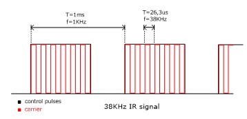
A common frequency used
for the carrier is 38KHz and control pulses frequency is in the range of
1-3KHz. The carrier signal is modulated by the control pulses and the resulting
signal is emitted by remote in IR band of electromagnetic spectrum. IR band is
invisible to human eye. You can see if an IR led is emitting light or not using
a camera. Point the camera to the led and you will see that light comes off.
Circuit description
IR signal is received by
TSOP1738. TSOP1738 is an infrared receiver at 38KHz. At the output of infrared
receiver we get a demodulated signal that means we get the low frequency
control pulses. Infrared receiver is powered from C1, R1 and Z1 that forms a 5V
power supply. With no signal received, infrared detector output is high and Q1
is on, so pin 4 of IC is LOW and 555 timer is in reset state. Q1 also acts as a
level shifter that converts 5V signal of TSOP1738 to 9V signal for IC1.

When HIGH control pulses
are appearing on TSOP1738 output then timer 555 (which is configured as an
oscillator) starts to oscillate are a preset frequency, for the duration of each
data pulse. That means that at pin 3 we get a signal that is similar to modulated
source signal. It has a carrier component and a control pulses component.
Oscillating frequency of 555 timer is set by R4 and C2 and pulse period is
given by:
T = 1,4 R4 C2
Trimmer R5 is used to fine
tune oscillating frequency at 38KHz. That’s equal to carrier frequency.
The output stage is formed from R6, Q2, one red LED, two IR
LEDs and two current limiting resistors R7 and R8. Q2 is connected as voltage
follower, that means when base of Q2 is HIGH transistor is ON allowing current
to flow through LEDs. LED current is set by R7 and R8 according the following
formula:

So IR
LEDs are emitting a signal that is similar to the signal received by TSOP1738,
that means it repeats the signal received at higher infrared radiation intensity.
The red LED is used as an optical indicator of output signal. Circuit can be
powered from a 9V battery.


Parts List
R1 = 1k
R2 = 3k3
R3 = 10k
R4 = 15k
R5 = 4k7 trimmer
R6 = 2k2
R7 = 470R
R8 = 47R – 1/2W
C1 = 47uF – 16V
C2 = 1n - polyester
C3 = 100uF – 16V
C4 = 47uF – 16V
Z1 = 5V1 zener
Q1 = BC549C
Q2 = BC337
IC1 = NE555
LED1 = red LED
LED2,3 = IR LED
IR receiver = TSOP138 or IR38DM
PCB
PCB is designed using Cadence Eagle.


Testing
Before powering the
circuit, remove IR LEDs. With no input signal red LED should be off. Now press
a button on a remote control, red led should flicker. If that’s the case then
your circuit should be working ok. Install IR LEDs. We found during testing
that IR signal emitted from remote and IR signal emitted from circuit are
interfering each other and that’s make receiving device not to react on
receiving the signal, this happens when IR from remote and IR from circuit’s
LEDs are on the same room. To solve that we must isolate the IR beam of remote
control. To do that we used a thin pipe in front of infrared sensor as seen in
photo below, so that the beam emitted from remote hits the sensor directly.
Another solution to this would be to put the emitting LEDs on a different room.

Installation
We installed the circuit
on the wall the way you see on the photo below. You can see that remote control
led is optically isolated from surround. You can also notice that one LED is
remotely placed near the device we would like to control.

Simple Touch Switch

Circuit Notes
|
The MPF102 (Q1) can be replaced with a NTE451 or ECG451, but still widely available. JFET-N-CHAN, UHF/VHF AMP
The 2N3565 (Q1/Q2) can be replace with a 2N2222(A), BC107, BC108, BC109(A/B/C), NTE123A, or ECG123A. The TIP31 (Q3) can be replaced with a NTE196 or ECG196, but is a common type and widely available. NO suffix.
The 'Touch Plate' can be anything non corrosive. I use a silver quarter. You can also use a small relay instead of the #53 bulb
R1 22Meg resistor
R2 47K resistor R3,R4 100K resistor R5,R6,R7 2K2 resistor C1 Capacitor, 22΅F, 25V C2 Capacitor, 22΅F, 25V Q1 MPF102 Q2,Q3 2N3565 Q4 TIP31 La1 Bulb, #53 |
Flood Detector
Introduction:
Last week I
had a big flood in my house. A water tube broke in the middle of the night
making lots of damage. Wooden floor, furniture, small electronic appliances,
all damaged due to the water. This made me think on a project that would sense
water on the floor and trigger an alarm.
The
detector should be able to sense water and trigger an alarm. Also it should be
small and battery operated. Battery ’s voltage
should be checked also.
Schematic:

Part
List:
R1 10K ohms resistor
R2 10K ohms resistor
R3 10K ohms resistor
R4 1K ohms
resistor
R5 10K ohms
resistor
R6 1K ohms
resistor
C1 100nF cap
Led1 5mm green led
Led2 5mm red led
D1 4V7 zener diode
Piezo Piezo HPE-120
VR1 78L05 regulator
IC1 12F683 SOIC microcontroller from Microchip
S1 Push button
Others:
Box
9V battery clip
PCB
Metal strips
Hex program for the
microcontroller
PCB:
The PCB used for this Project is
single layer and its size is 27.02
mm x 32.41mm.
The SOIC version of the
microcontroller helps to reduce the size of the PCB.
Top
Side
Here is the top view with the
components

Bottom
Side

Box
and probes:
I tried to find a small box that
would fit both circuit and box. This way it would be more discrete.
The box that I used did not had enough room
for all components, so I had to place both leds and piezo on the exterior of
the box. That detail didn’t make any difference since the leds should stay
visible and the piezo free to make the loudest sound possible.
The probes can be made from any
conductive material, but I preferred not to use copper because it deteriorates
with time. In my opinion a good material to be used is stainless steel or
aluminium. However, maintenance should be done from time to time checking the
probes and testing them with water.
Also, the probes should be placed
not to far apart from each other and they never should touch each other. The
more probe area available for water sensing the better.
The probes I used in my project
are made from aluminium.


The final
assembly looks like this:

The
detector is placed on the floor. It’s possible to use some double side tape and
stick the detector against the wall or just leave it like the picture below.
The probes are on the bottom of the box touching the floor and the leds on the
top

Hex
Program:
The Hex
program must be saved in the microcontroller’s memory before soldering on the
PCB.
Testing:
Turning on
the circuit, both leds and piezo are tested. Also the probes are checked. If
the probes are sensing water or any kind of leakage it will turn on the red led
and it will trigger the piezo.
After everything
is checked ok the detector will enter it’s normal state.
Every 10
seconds it will check the probes and the battery’s voltage.
If water
gets between the probes the detector will enter the alarm mode where the red
led will turn on and the piezo will start making a loud sound. The detector
will keep itself in alarm mode until S1 is pressed.
If the
battery’s voltage is good, the green led will flash every 10 seconds but if the
voltage reaches 7V the red led will flash every 10 seconds and the piezo will
make a short sound to indicate it’s time to change the battery.
The water
detection time is less than 10 seconds. Since the microcontroller enters a low
consumption state between readings to preserve battery life, this state is
always 10 seconds long. If water reaches the probes while being in the low
power state it will have to wait until it finishes the sleep state before it
can trigger the alarm.
Conclusion:
iButton Electronic Lock
Since iButton DS1990A introduced
in market from Dallas Semiconductor (MAXIM), it has been used in many applications concerning
security, access control systems etc. In this project we will use iButton as a
key to an electronic lock. This electronic lock can use many different kinds of
iButtons and can store up to 9 different keys. One of the keys is the master
key and is permanent stored in memory. With the use of master key we can add or
remove slave keys.
This electronic
lock can be used with any type of iButtons you may already have, since the only
thing needed is the internal serial number, that’s different for every iButton.
The command used to read the serial number is the same for all iButtons. The
iButton family code that goes with every iButton, can be anything and is
calculated as part of the whole serial number. We must also notice that DS1990A
series iButtons are the cheapest.

This electronic
lock designed to work stand-alone and it’s easy to construct. What the user
sees (outside of the door for example) is a iButton socket and a led. From
inside the door, we can open it using a simple push button. For the actual lock
of the door a solenoid and a bold are used. Solenoid must be rated at 12Vdc.
iButtons serial numbers stored in memory can be removed and updated when
needed. One master key is used to manage the rest of them. Totally a number of
9 different keys can be stored in memory.
Schematic diagram is
shown at figure 1. The circuit is build around an Atmel AT89C2051(U1)
microcontroller. The port 1 (P1) of mcu is used to connect a 7-segment common
anode led display. This led display will be used on the programming of
additional keys. For the same reason a push-button labelled SB1 is connected on
P.3.7. Storage of iButtons serial numbers is done on a 24C02 EEPROM (U3). It is
connected on P3.4 (SDA) and P3.5 (SCL) of U1. The external iButton socked is
connected on port P3.3 via XP2 pin array. The rest of components VD4, R3, VD5 and VD6 are used for protection
of mcu ports. One pull-up resistor R4 is used as required from 1-wire protocol.
An additional iButton socket is connected parallel with the predefined at pins
XS1. This one is used for programming the keys. The door OPEN button is
connected on P3.2 through XP1 connector, using the same protection components
as above. The solenoid that does the lock is connected on XT1 connector.
Solenoid is controlled from a power MOSFET IRF540 (VT3). Diode VD7 is added to
protect MOSFET from voltage strikes due to solenoid inductance. Transistor VT3
is controlled from VT2, which reverses the logic state that’s appears on P3.0,
so on VT3 we have output 0V and 12V. This additional transistor is useful as it
translates the mcu logic levels to 0V and 12V, capable to drive the solenoid.
Fig.1 Schematic diagram of iButton electronic lock
A led is used to indicate the state of the electronic
lock, which is controlled from the same pin as the solenoid, using transistor
TV1. This led is connected to the board using the same pin array XP2. But we
need to ensure that the circuit will always work without supervision. For that
reason we added ADM1232 (U2) that does the mcu reset pin control. This chip
have a counter and voltage test circuits inside it. On pin P3.1 mcu produces
pulses when it works right. If for a reason mcu freeze then U2 send it a reset
pulse and work is resumed.
This electronic lock has it’s own power supply on board, consisting of
transformer T1, bridge rectifier VD9-VD12 and voltage regulator U4. As power
backup an array of 10 AA batteries is used (BT1-BT10). Total capacity is 800mAH. When the circuit is connected on
main voltage the battery pack is charged via R10 with a current of 20mA. This
current is equal to 0.025C (where C is the batteries capacity) and that’s a
very small current depending on total capacity. That’s put the battery on a
steady charge to compensate losses among time and no charge completion
detection is needed. That can be done as the excess energy is consumed in heat,
that can not harm batteries as its low.
Overall board dimensions are 150х100х60mm. The most components are placed on the board, including the
transformer. Batteries are placed on battery holders. In the place of AA
batteries we could use a 12V sealed Lead – Acid battery. External components
are connected on board with 2 or 3 pin connectors. Part numbers HG1, SB1 and XS1 are used only in programming
mode so can be placed inside the plastic enclosure. Led VD3 can be placed on
the face of enclosure, to indicate
proper powering of board. A connection diagram is show on figure 2.

Fig.2 Connection diagram
When the door goes open, a 3 sec pulse is triggering the solenoid. When
we press the door open button the door remains open as long as we push it.
The electronic lock can register 9 keys, plus one master key. Master’s
serial number is stored inside mcu. The rest of keys are stored on the external
memory under slot 1 to 9. To add or remove a new key you should have the master
key. Also master key can be used to open the door.

Fig. 3 Programming steps for adding a new key
To add a new key, the following steps should followed:
- Press programming button.
- Led displays letter «P» that indicated
you entered programming mode.
- Touch the master button in socket.
- Led displays number «1». That’s the current
selected slot in memory.
- Push the programming button to select a different
programming slot for your new key.
- Touch the new key to the socket.
- The number on led display blinks, indicating
ready to program.
- Touch again the new key to confirm registration
to memory.
- If successfully registered the display stops
blinking.
- After 5 seconds, the program exits from
programming mode.
The programming
procedure to register a new key is displayed schematically on figure 3.
If you want to register more keys, then from step 9 you can go directly
to step 5. These steps can be revised as many times as you like.
If after step 7, you find out that you selected wrong slot number and
you don’t want to loose that key, press programming button or just wait 5
seconds. When you press the button the slot number increases by one and memory
hasn’t changed yet. If you wait 5 seconds, programming mode will exit and
nothing is going to register in memory.
Generally in any programming step, you can wait 5 second to exit programming
mode.
To remove an already registered key, you follow an almost same
procedure, using only the master key. Basically, it’s like registering the
master key on the memory slot you would like to erase. This procedure is shown
on figure 4.

Fig.4 Programming steps for removing a key.
During programming
mode, the door will only open with the press of the OPEN button. Also, because
the two iButton sockets are connected in parallel, you should avoid simultaneous
touch of keys on both sockets.
Master’s key serial number is stored on mcu’s program memory, beginning
from address 2FDH. The length of serial number is 8 bytes. The serial must be
equal that is printed on top the iButton case, reading from left to right. On memory address 2FDH the control byte is
registered, then on address 2FEH - 303H the
next six bytes are registered, beginning with most significant byte. Finally
the family code byte is stored on address 304H. For example a complete serial
code should look like: 67 00 00 02 D6 85 26 01
The software block diagram shows on figure 5. The
program starts, asking if a key has entered. If a key is entered, then it goes
on reading the internal serial number. The next step is to check if this is the
master key or another key already registered in memory. If the key is verified
then the door is opened. Also the OPEN push button is checked, and if it’s
pressed the door opens.

Fig.5 Software block diagram
For the programming mode there exists two subprograms: PROGT and PROGS, whose block diagrams
show in figure 6. The first is called when the serial number is read, in the
programming phase and the second is called when the programming button is
pressed. Programming of a new key is completed in three phases. When we press the programming button, we enter the programming mode. In this state
the led displays «P» and the serial number of the
key is checked to see if this is the master key, because this key is required
to proceed on programming steps.
If this is the master key, we proceed on phase 2. Now, led is displaying
the number of current selected memory slot, changing by pressing programming
button. If we touch the key again, then it is registering on memory and we pass
to phase 3. If we touch another key, this is also registered and we pass to phase
2. With the press of the button, we pass on phase 2 without registering any
key.
If we don’t touch
anything in a period of 5 seconds, the program exits from programming mode.
Block diagrams of figure 5 and 6 are simplified, but they give as an
overall sense of program functionality.
It’s upon your
desire to extend the capabilities of this program, as it’s open source, to fit
your special needs.

Fig.6 Programming mode
subprograms block diagrams


